
Manufacturing case study
From Design to Finished Part: A Custom Laser-Cut Aluminum Enclosure
How a customer concept became a manufacturable aluminum assembly through CAD design, manufacturability review, laser cutting, forming, welding and powder coating.
Getting a custom metal part made involves more than sending a file to a laser cutter.
The details matter: material selection, cut geometry, bend locations, mounting features, assembly methods and finishing requirements.
For this project, we developed a decorative aluminum cover from an initial customer requirement into a finished fabricated assembly.
The process illustrates how a design can be reviewed and prepared for manufacturing before any material is cut.
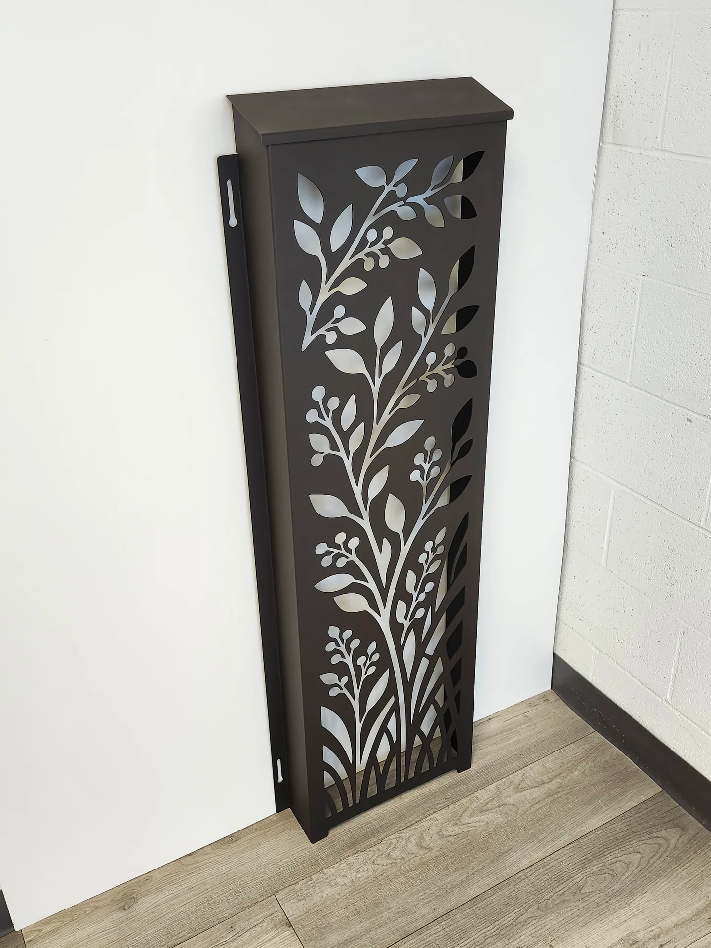
Part Snapshot
- Material
- 5052 aluminum
- Processes
- Laser cutting, forming, aluminum welding, assembly and powder coating
- Finish
- RAL 8025 bronze-brown powder coat
- Dimensions
- 15" inside width, approximately 4" inside depth, 51" front height and 52.5" rear height
- Key features
- Decorative laser-cut pattern, sloped top and elongated mounting slots
- Design documentation
- SolidWorks 3D model and manufacturing drawing
- Quantity
- One custom assembly
- Deliverable
- Finished aluminum cover, ready for customer installation
The Starting Point: A Concept That Needed Manufacturing Detail
The customer wanted a custom aluminum cover to conceal exposed piping on an exterior wall.
The requirements included sufficient clearance around the piping, a sloped top to shed rainwater, convenient mounting and a decorative botanical pattern.
The project began with a photograph, approximate dimensions and the customer's preferences.
An initial AI-assisted concept helped establish the intended appearance.
However, a concept image doesn't define the details needed for reliable manufacturing.
Before cutting, the design needed to be developed into a practical aluminum assembly.
1. Developing the CAD Model
The concept was translated into a detailed 3D assembly using SolidWorks.
The model defined the aluminum components, overall dimensions, sloped top and mounting arrangement.
The customer requested an increase in inside width from 12" to 15" to provide additional clearance for the piping and installation.
This change was incorporated before production.
The 3D model provided a practical basis for reviewing the geometry and preparing manufacturing documentation.
2. Reviewing the Design for Manufacturability
A design can look correct on screen and still present problems during cutting, forming, welding or installation.
For this project, several important details were considered and refined before manufacturing.
Laser-cut pattern
The botanical cutout design was adapted for laser cutting, with attention to the remaining material between openings and the rigidity of the finished panel.
Dimensions and fit
The inside width was increased to 15 inches, and the overall geometry was established around the installation requirements.
Mounting features
Elongated mounting slots were incorporated into the side panels instead of conventional round holes. This allows the assembly to slide over pre-installed fasteners, simplifying installation and future removal.
Formed and welded construction
The aluminum components were developed as a fabricated assembly, with geometry suitable for cutting, forming, fitting and welding.
Outdoor application
The sloped top and powder-coated finish were incorporated into the design for its intended exterior application.
These decisions demonstrate why reviewing a design before production is important.
A manufacturability review helps identify details that should be clarified or adjusted before material is cut, rather than discovering problems during fabrication or assembly.
What We Also Look For in Customer-Supplied Files
Depending on the project, our review may consider:
- Small cutouts, narrow bridges and sharp internal features.
- Hole and slot sizes.
- Bend locations and material around bends.
- Material thickness and fabrication feasibility.
- Fit-up requirements for welded assemblies.
- Coating and finishing requirements.
- Missing dimensions or unclear manufacturing specifications.
These are examples of issues that may need attention on different projects, not a claim that every issue occurred or was corrected on this particular enclosure.
3. Preparing the Manufacturing Drawing
Once the design was finalized, a dimensioned manufacturing drawing was prepared.
The drawing documented the material specification, overall dimensions, assembly geometry and mounting features required for production.
Clear manufacturing documentation is especially useful when a project involves several manufacturing processes.
Select the drawing to enlarge it. View original drawing (PDF) (opens in a new tab)
4. Laser Cutting, Forming and Assembly
With the design approved, the aluminum components moved into production.
The parts were laser-cut and formed to the required shapes, then fitted and welded into the completed assembly.
The finished fabrication incorporated the decorative pattern, sloped top and mounting features defined during the design stage.
5. Powder Coating and Finished Product
After fabrication, the cover received a bronze-brown powder-coated finish in RAL 8025.
The result was a completed aluminum assembly combining the required dimensions, mounting arrangement, decorative pattern and exterior finish.
The finished cover was delivered to the customer, who was pleased with the result.
This project illustrates how a design can move from initial requirements through manufacturing preparation and multiple fabrication processes to a finished product.